Instrument Host Overview
========================
For most Voyager experiments, data were collected by instruments on the spacecraft. Those data were then relayed via the telemetry system to stations of the NASA Deep Space Network (DSN) on Earth. Radio Science experiments (such as radio occultations) required that DSN hardware also participate in data acquisition. The following sections provide an overview first of the spacecraft and then of the DSN groundsystem as both supported Voyager science activities.
Instrument Host Overview - Spacecraft
=====================================
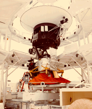
The Voyager 1 and Voyager 2 spacecraft were identical and were built by the Jet Propulsion Laboratory (JPL). With a mass of 815 kilograms, each carried its own power, propulsion, andcommunications systems and its own science instruments.
Spacecraft electrical power was supplied by RadioisotopeThermoelectric Generators (RTGs) that produced about 400 watts.
The Attitude and Articulation Control Subsystem (AACS), Computer Command Subsystem (CCS), and Flight Data Subsystem (FDS) managed spacecraft operations. Thrusters and gyrosprovided physical propulsion and attitude control.
Communications between the spacecraft and Earth were carried out via a high-gain radio antenna using both S-band and X-bandfrequencies at data rates as high as 115.2 kilobits per second.
A Digital Tape Recorder (DTR) could save up to 500 million bits when no Earth station was available for real-time data transmission. Voyager control systems could record sets of several thousand instructions, allowing autonomous operation for days or weeks at a time. More information on the spacecraft can be found in [MORRISON1982], [KOHLHASE1989], and[JPLPD618-128].
The spacecraft itself was built around its 'bus' -- a decagonal prism, which was about 2 meters in diameter and about 60 cm deep. Each of the ten sides of the bus was associated with a 'bay' containing engineering systems or science instrument electronics. Bay 1, for example, contained the radio transmitter. The High-Gain Antenna (HGA) was mounted to the end of the bus facing Earth. The bays were numbered 1 through 10 in a clockwise direction when viewed from Earth. Extending away from the bus were three booms: a science boom and scan platform to which most instruments were mounted, a magnetometer
more ...
Available Data
External Reference
|
|
 |
Privacy / Copyright Freedom of Information Act |
 |
Web Master: PDS-PPI Operator NASA Official: Becky McCauley-Rench |