Instrument Host Overview
========================
The main source for this text is the National Space Science Data Center.
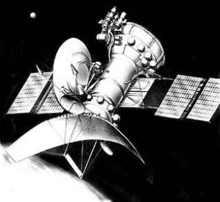
The spacecraft was based on modifications to the orbiter portions of the Venera 9 and 14 probes. It consisted of a 5 m long cylinder with a 6 m diameter, 1.4 m tall parabolic dish antenna for the synthetic aperture radar at one end. A 1 meter diameter parabolic dish antenna for the radio altimeter was also located at this end. The electrical axis of the radio altimeter antenna was lined up with the axis of the cylinder. The electrical axis of the synthetic aperture radar deviated from the spacecraft axis by 10 degrees. During imaging, the radio altimeter would be lined up with the center of the planet (local vertical) and thesynthetic aperture radar would be looking off to the side at 10 degrees.
A bulge at the opposite end of the cylinder held fuel tanks and propulsion units. Two square solar arrays extended like wings from the sides of the cylinder. A 2.6 m radio dish antenna for communications wasalso attached to the side of the cylinder.
Available Data
External Reference
|
|
 |
Privacy / Copyright Freedom of Information Act |
 |
Web Master: PDS-PPI Operator NASA Official: Becky McCauley-Rench |